")
El MPU6050 IMU tiene un acelerómetro de 3 ejes y un giroscopio de 3 ejes integrados en un solo chip. El giroscopio mide la velocidad de rotación o la tasa de cambio de la posición angular a lo largo del tiempo, a lo largo de los ejes X, Y y Z. Por otro lado, el acelerómetro MPU6050 mide la aceleración de la misma manera que se explicó en el video anterior para el sensor del acelerómetro ADXL345. Brevemente, puede medir la aceleración gravitacional a lo largo de los 3 ejes y usando algunas matemáticas de trigonometría podemos calcular el ángulo en el que está posicionado el sensor. Entonces, si fusionamos o combinamos los datos del acelerómetro y el giroscopio, podemos obtener información muy precisa sobre la orientación del sensor. La IMU MPU6050 también se denomina dispositivo de seguimiento de movimiento de seis ejes o dispositivo de 6 DoF (seis grados de libertad), debido a sus 6 salidas, o las 3 salidas de acelerómetro y las 3 salidas de giroscopio.
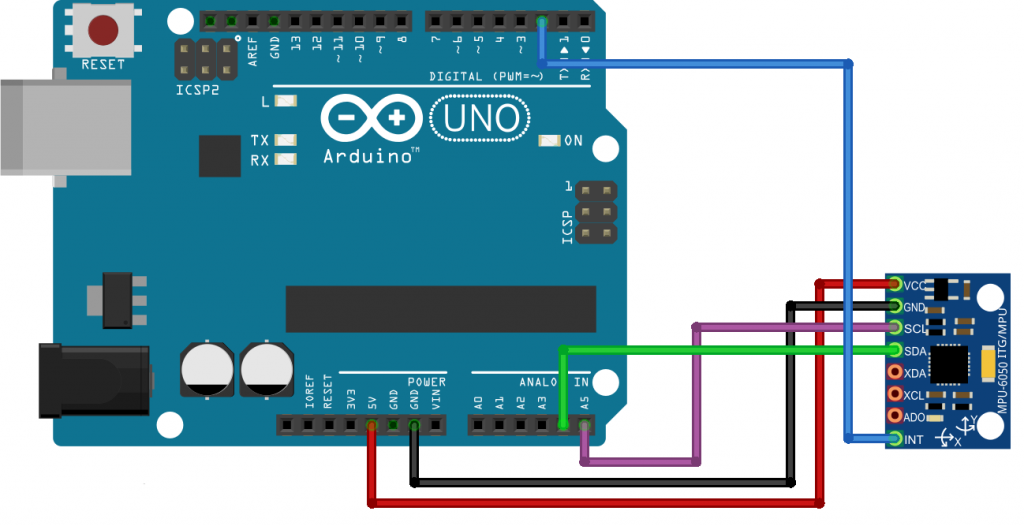
Diagrama de conexión
Librerías para el sensor MPU6050
Descarga de las librerías:
https://microlab.ec/blog/wp-content/uploads/2021/05/MPU6050.zip
https://microlab.ec/blog/wp-content/uploads/2021/05/I2Cdev.zip
Los archivos se deben descomprimir y pegar en la carpeta que contiene todas las librerías de Arduino: C:\Program Files (x86)\Arduino\libraries
Ejemplo de código
#include "I2Cdev.h"
#include "MPU6050.h"

// Arduino Wire library is required if I2Cdev I2CDEV_ARDUINO_WIRE implementation
// is used in I2Cdev.h
#if I2CDEV_IMPLEMENTATION == I2CDEV_ARDUINO_WIRE
    #include "Wire.h"
#endif

// class default I2C address is 0x68
// specific I2C addresses may be passed as a parameter here
// AD0 low = 0x68 (default for InvenSense evaluation board)
// AD0 high = 0x69
MPU6050 accelgyro;
//MPU6050 accelgyro(0x69); // <-- use for AD0 high

int16_t ax, ay, az;
int16_t gx, gy, gz;


// uncomment "OUTPUT_READABLE_ACCELGYRO" if you want to see a tab-separated
// list of the accel X/Y/Z and then gyro X/Y/Z values in decimal. Easy to read,
// not so easy to parse, and slow(er) over UART.
#define OUTPUT_READABLE_ACCELGYRO

// uncomment "OUTPUT_BINARY_ACCELGYRO" to send all 6 axes of data as 16-bit
// binary, one right after the other. This is very fast (as fast as possible
// without compression or data loss), and easy to parse, but impossible to read
// for a human.
//#define OUTPUT_BINARY_ACCELGYRO


#define LED_PIN 13
bool blinkState = false;

void setup() {
    // join I2C bus (I2Cdev library doesn't do this automatically)
    #if I2CDEV_IMPLEMENTATION == I2CDEV_ARDUINO_WIRE
        Wire.begin();
    #elif I2CDEV_IMPLEMENTATION == I2CDEV_BUILTIN_FASTWIRE
        Fastwire::setup(400, true);
    #endif

    // initialize serial communication
    // (38400 chosen because it works as well at 8MHz as it does at 16MHz, but
    // it's really up to you depending on your project)
    Serial.begin(38400);

    // initialize device
    Serial.println("Initializing I2C devices...");
    accelgyro.initialize();

    // verify connection
    Serial.println("Testing device connections...");
    Serial.println(accelgyro.testConnection() ? "MPU6050 connection successful" : "MPU6050 connection failed");

    // use the code below to change accel/gyro offset values
    /*
    Serial.println("Updating internal sensor offsets...");
    // -76	-2359	1688	0	0	0
    Serial.print(accelgyro.getXAccelOffset()); Serial.print("\t"); // -76
    Serial.print(accelgyro.getYAccelOffset()); Serial.print("\t"); // -2359
    Serial.print(accelgyro.getZAccelOffset()); Serial.print("\t"); // 1688
    Serial.print(accelgyro.getXGyroOffset()); Serial.print("\t"); // 0
    Serial.print(accelgyro.getYGyroOffset()); Serial.print("\t"); // 0
    Serial.print(accelgyro.getZGyroOffset()); Serial.print("\t"); // 0
    Serial.print("\n");
    accelgyro.setXGyroOffset(220);
    accelgyro.setYGyroOffset(76);
    accelgyro.setZGyroOffset(-85);
    Serial.print(accelgyro.getXAccelOffset()); Serial.print("\t"); // -76
    Serial.print(accelgyro.getYAccelOffset()); Serial.print("\t"); // -2359
    Serial.print(accelgyro.getZAccelOffset()); Serial.print("\t"); // 1688
    Serial.print(accelgyro.getXGyroOffset()); Serial.print("\t"); // 0
    Serial.print(accelgyro.getYGyroOffset()); Serial.print("\t"); // 0
    Serial.print(accelgyro.getZGyroOffset()); Serial.print("\t"); // 0
    Serial.print("\n");
    */

    // configure Arduino LED for
    pinMode(LED_PIN, OUTPUT);
}

void loop() {
    // read raw accel/gyro measurements from device
    accelgyro.getMotion6(&ax, &ay, &az, &gx, &gy, &gz);

    // these methods (and a few others) are also available
    //accelgyro.getAcceleration(&ax, &ay, &az);
    //accelgyro.getRotation(&gx, &gy, &gz);

    #ifdef OUTPUT_READABLE_ACCELGYRO
        // display tab-separated accel/gyro x/y/z values
        Serial.print("a/g:\t");
        Serial.print(ax); Serial.print("\t");
        Serial.print(ay); Serial.print("\t");
        Serial.print(az); Serial.print("\t");
        Serial.print(gx); Serial.print("\t");
        Serial.print(gy); Serial.print("\t");
        Serial.println(gz);
    #endif

    #ifdef OUTPUT_BINARY_ACCELGYRO
        Serial.write((uint8_t)(ax >> 8)); Serial.write((uint8_t)(ax & 0xFF));
        Serial.write((uint8_t)(ay >> 8)); Serial.write((uint8_t)(ay & 0xFF));
        Serial.write((uint8_t)(az >> 8)); Serial.write((uint8_t)(az & 0xFF));
        Serial.write((uint8_t)(gx >> 8)); Serial.write((uint8_t)(gx & 0xFF));
        Serial.write((uint8_t)(gy >> 8)); Serial.write((uint8_t)(gy & 0xFF));
        Serial.write((uint8_t)(gz >> 8)); Serial.write((uint8_t)(gz & 0xFF));
    #endif

    // blink LED to indicate activity
    blinkState = !blinkState;
    digitalWrite(LED_PIN, blinkState);
}
Si necesitas asesoría en proyectos de Arduino, Raspberry, electrónica, estamos localizados en la ciudad de Quito Ecuador. Somos Microlab.
Dejar una contestacion